Description
Usage
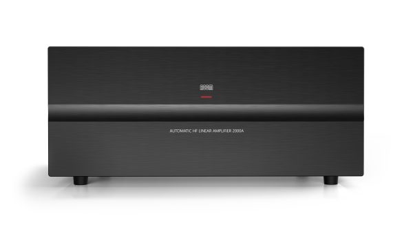
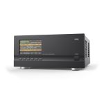
The ACOM 2000A Automatic HF Linear Amplifier is the world’s most advanced HF amplifier designed for amateur use. The ACOM 2000A is the first amateur HF amplifier to include both fully automatic tuning and sophisticated digital control capabilities. This revolutionary new amplifier delivers maximum legal power in all modes and operates on all HF amateur bands.
A New standard in amplifier features and performance
The ACOM 2000A represents a major advance in the state-of-the-art in HF amplifier design. It changes forever the way radio amateurs employ HF power amplifiers in their stations.
Instantaneous, automatic tuning makes slow, cumbersome band changes a thing of the past.
A built-in, wide-range antenna tuner matches loads with high SWR (up to 3:1), often eliminating the cost and complexity of an external, high-power antenna tuner.
Advanced protection circuits ensure amplifier safety under every potential combination of operating conditions.
Remote diagnostic features and modular design ease fault isolation and repair.
Cutting-edge technology enhances a classic design
At the core of the ACOM 2000A is a classic HF amplifier design, employing two 4CX800A high performance ceramic metal tetrodes operating in a grid-driven configuration.
This design was chosen for its inherent stability and extremely low production of spurious emissions. ACOM coupled this tried-and-true configuration with today’s most advanced digital control technology to create an amplifier with outstanding performance, features and reliability.
Matched pair tube operation
Starting January 1st, 2024, a NEW matched pair ACOM 4CX800A high-performance ceramic-metal tetrode is used for maximum efficiency.
Till the end of 2023, the amplifier was produced with Svetlana GU74B (4CX800A) tubes.
Clean signal
Grid-driven tetrodes, cathode negative feedback, excellent transceiver loading (typically below 1.2:1 input SWR), and regulated SG voltage result in an extremely low distorted output. Measured typical IMD are – 40 dB (3rd order) and – 45 dB (5th order). Classical Pi-L network, all-air coils (no ferrite), and carefully designed layout of the output tank offer typical harmonic emissions as low as – 55 dBc (second) and below – 70 dBc (third and above). Thus, probability of QRM, BCI or TVI is dramatically minimized.
Automatic tuning
The automatic tuning features in the ACOM 2000A represent a real breakthrough in HF amplifier design. Never think about an ATU for SWR up to 3:1 (2:1 on 160 m). Matching the actual antenna impedances to the optimum tubes load is completely automated. Typically 1 second and no skill is required. By completely eliminating time-consuming tune-up procedures, the ACOM 2000A has gives contesters a real edge. It is now possible to change bands without a moment’s thought. You can work every multiplier spotted using software point-and-shoot – regardless of band. And always know the amp is properly tuned and operating safely.
The amplifier follows your transceiver’s band and frequency automatically in less than a second. No special cables are required. Just a dot on CW or “Ah” on SSB are enough.
The ACOM 2000A breaks every amateur band into multiple frequency segments. The user can store up to 10 sets of tuning adjustments for every frequency segment – allowing individual settings for multiple antennas on each band. SWR can increase considerably when an antenna is operated away from its resonant frequency. Unlike other amplifiers on the market today, the ACOM 2000 output matching network allows the amplifier to operate at full power, even with SWR as high as 3:1 (2:1 on 160 m).
Advanced digital control
Microprocessor control improves performance and makes possible a wide range of new, advanced features.
QSK
Full break-in (QSK) based on a built-in vacuum relay. Transmit/receive switching sequence is secured by a dedicated microprocessor.
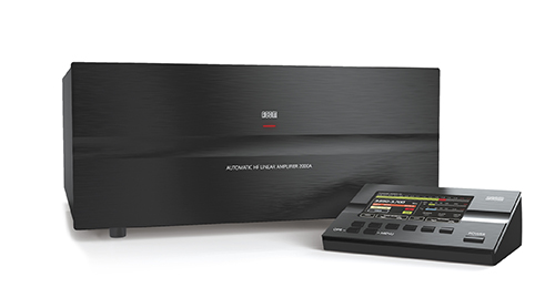
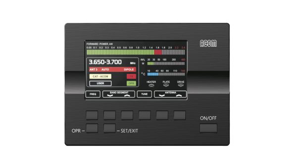
Remote Control Unit
Only the Remote Control Unit needs to be placed near the operator. The main unit can be installed up to 3 meters (10 feet) away. RCU features include: amplifier status shown on LCD display, control of all functions, measuring and/or monitoring of the 20 most important parameters, on-board technical assistance, troubleshooting suggestions, record of power-on hours, password provided.
Protection
All tubes voltages and currents, supply voltages, overheating, overdrive, insufficient flow of cooling air, internal and external RF arcs (in the amplifier, antenna selector, tuner or antennas), T/R sequencing, antenna relay contact hot switching, antenna matching quality, reflected power, stored data, inrush power-on current, and cover interlock for operator safety. Antenna matching can be achieved in less than 10 seconds and at a quarter of nominal output power, which produces lower risk of interference to other stations and greater safety to the amplifier components.
Easy maintenance
The protection system makes damaging the amplifier a difficult job. Information on the 12 most recent protection trips is stored in the memory for remote diagnostics via PC or Internet.
Remote control capabilities
Remotely controlled by RS-232 port and via the Internet by the ACOM eBox Ethernet Remote Control device.
ACOM eBox device permits full integration into any computer-driven station configuration. All functions are accessible from a PC via Internet browser. Local network may include more than one amplifier/antenna unit set working in a system.